BME ISP: Temperature/Humidity Sensor with Cloud Storage
In B-Term 2017, Maria Daigle (class of 2019) completed an independent study project with Prof. Albrecht to improve the lab atmospheric monitoring process. This report will teach you how to build the temperature and humidity sensing system with connectivity to cloud storage on thingsboard.wpi.edu.
Background
In the Quantitative Neurotechnology lab, experiments are very sensitive to fluctuations in atmospheric temperature and humidity. The current system of writing down the temperature and humidity when conducting an experiment is not working well enough. The proposed solution to this problem is to create a system which would automatically and continuously log the temperature and humidity and store this information in a cloud-based data collection system. This way, the lab always has access to this data and can look back on any date and time to find out whether an experiment may have been affected.
The solution
To accomplish this, I began with research to determine what this system might look like and the kinds of parts I would need. After a detailed review of my options, we got some parts and wired them together on a breadboard. The final product consists of a microcontroller with wifi capability, a an LED display, and a temperature/humidity sensor. It collects data every 2 minutes, displays the latest value on the LED as well as graphs of the past two hours, and sends the data to the cloud server. On the server side, the data is stored and visualized at thingsboard.wpi.edu:8080 and can be accessed from anywhere.
Useful background knowledge
As I was working through these problems, I realized that despite my background in electrical engineering, I knew very little about digital circuitry. Luckily, there are a wealth of tutorials online that explain the basic knowledge necessary to complete this project. These are the topics that I had the least familiarity with and that you might need to know to complete a project like this.
– Binary
– I2C
Choosing parts
These are the parts that we chose to use. The sensor has the best balance of compact size and high accuracy in its price range. The Feather board comes with built-in wifi, which makes it much easier to use than the other wifi chip options out there. OLED display fits perfectly on top of the Feather board and is just the right size to fit everything it needs. The battery is rechargeable, so it will allow the device to continue running uninterrupted whenever USB power is unavailable.
SHT31-D breakout board Temperature and Humidity sensor
Feather HUZZAH w/ ESP8266 WiFi
Adafruit FeatherWing OLED display – 128×32
Lithium Ion Polymer Battery 3.7v 1200mAh
Building and Coding
o Feather HUZZAH board
This board comes with built-in wifi capabilities, which is especially convenient because many of the other wifi chip options (even other versions of the ESP8266) have poor reviews and seem more difficult to work with. To set up the board, all you need are the drivers and libraries, and some example code to get you started. Adafruit’s tutorial has everything you need to know! I used the Arduino IDE to code this project, so I had to install the CP2104 Driver and ESP8266 Package; then I used Adafruit’s example code to test out my wifi connection. All of this is available here.
Note: to get on WPI wifi, you have to register the device with its MAC address on the WPI netreg site before you’ll be able to connect to the internet. There are many ways to find the MAC address, but what I did was I connected to my personal wifi at home, then I used an app on my phone ‘Network Scanner’ for Android to find the MAC address. I used that to register the device at the WPI netreg. When you connect to the WPI-Open network, just delete the password sections in the code.
o Adding the OLED Display
The Adafruit tutorial on the OLED display will get you started with assembly and demo code. It only needs to be soldered onto the feather board. Then, download the SSD1306 and GFX libraries available here to get started with programming it. The sample code will allow you to try it out right away!
o Adding the SHT31-D Sensor
Once again, Adafruit’s tutorial has everything you need to know about using this sensor. Wiring it up to the board is super simple — since it includes just 4 wires, I’m not including a wiring diagram, but I will include a photo of the final product. Just connect the Vin to the power supply (labeled 3V), connect GND to GND, connect SCL to SCL (pin 5), and SDA to SDA (pin 4). The pinout diagram for the feather board was good to consult for this.
After downloading the SHT31 library, the demo test file should let you try out the sensor immediately; all of this is very well explained here.
o Connecting them all together
· General tips for Arduino coding
Before starting this project, I had no experience with coding for Arduino; this reference was useful in figuring out the language. Here are some important lessons learned from coding mistakes that I made so you don’t have to:
- Make sure it follows this general form (i.e., don’t put the ending curly bracket in the wrong place):
void setup(): {
// everything you want to happen only once
}
void loop(): {
//everything that will loop continuously
}
- You can create other functions following the same format, and call them within the setup() or loop() functions
- Variable definitions need a “;” after them
- When working with the OLED:
- Use “display.clearDisplay();” (without it, adding more text writes over itself and then you can’t read any of it)
- Even more important is “display.display();” — without it nothing will actually show up
- This display has room for about ~21 characters per line, and 4 lines; any more will get cut off (assuming you use size 1 text)
- This tutorial nicely breaks down what you need to know about the OLED — but the example used within it is for the 128×64 display. I’m using the 128×32 display, so everything from the tutorial (on the y axis) must be cut in half
· Display temperature and humidity data on the OLED
Here’s a simple way to get started: read from the SHT sensor and display it on the OLED. This is the code that I used to accomplish that:
https://codebender.cc/sketch:630333
Once you’re comfortable with this, try something a little more complicated: create graphs from the sensor data to display on the OLED.
https://codebender.cc/sketch:630273
Next, we’ll combine this with the wifi capability to upload this information to the cloud and visualize it there.
· Thingsboard
Thingsboard is an open-source platform that we have set up to be hosted on a WPI server for anyone at WPI to use. You can access it at thingsboard.wpi.edu:8080; to set up your own account, contact Ermal Toto in Research Computing at toto@wpi.edu.
Thingsboard allows you to send data from your internet-enabled devices to their cloud data storage system and visualize it in realtime. It’s not extremely user-friendly, but the getting started guide covers the basics pretty well.
There are several ways to connect to Thingsboard — you can use MQTT, HTTP, or CoAP protocols — but to the best of my knowledge, Arduino supports MQTT much better than the other two. To learn a little bit about the MQTT protocol, I suggest the broad overview given in Adafruit’s tutorial. However, we are not using the Adafruit IO (a similar platform to Thingsboard), so the more specific things don’t apply.
The Thingsboard getting started guide above could be useful if you use Node.js and NPM, or Mosquitto, or you want to use the CoAP or HTTP protocol, but I did not have these capabilities on my computer so I sought a different solution. I referenced this example, which uses a temperature sensor and ESP8266 wifi chip to push data to the thingsboard server. A little modification of their code (and a non-WPI network) was all I needed to get this working. You will also need to download PubSubClient library, available in the example or on Github for this to work. You can skip straight to my code below to test this out for yourself.
This code will connect to the internet, read temperature and humidity from the SHT31 sensor, and send the data to Thingsboard via MQTT. Note: if you are not on WPI-Open, change your wifi network name, uncomment the line “#define WIFI_PASSWORD “yourwifipassword”” and include the password when connecting to the internet like this:
WiFi.begin(WIFI_AP, WIFI_PASSWORD);
https://https://codebender.cc/sketch:630323
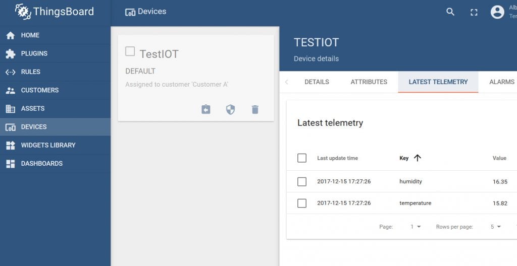
You can check to make sure that Thingsboard is receiving your data by checking the latest telemetry from your device.
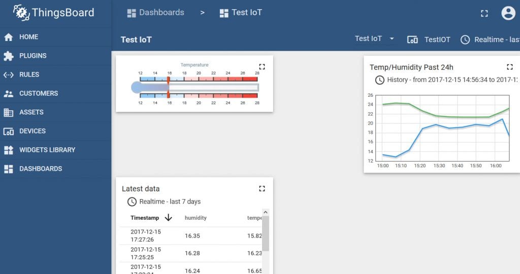
Once Thingsboard is successfully receiving data, you can create widgets on your dashboard to visualize the data.
Finally, we will combine everything. Connect to the internet, read temperature and humidity from the SHT31, display the data on the OLED with graphs that you can go between using the buttons on the display, and send the data to Thingsboard.
As a review, here are all of the libraries and drivers you will need to install in order to use this code or make modifications to it:
https://https://codebender.cc/sketch:630313
That’s it! This can run on USB or battery power; I’m using a 3.7V LiPoly rechargeable battery that will allow it to sit in the lab as a standalone system.


